|
  

Pitot-Static System
Running Total Hours:
0.0
 | 2008.04.26: (0.0)
I found Van's static air kit to be quite cheesy and unworthy of being
installed in an airplane, especially an IFR airplane. For
starters, the static ports themselves are nothing more than pop rivets
with the mandrels punched out, glued into the fuselage skin, and with
plastic tubing slipped over the hollow barrel, and gobbed over with
RTV to hold it together and form a seal. As one would expect,
many builders have reported trouble with leaks and/or total
separation. Furthermore, the static air kit provides a variety
of non-standard platic tubing in different sizes and materials
(whatever Van's found in somebody's scrap heap???) that are supposed
to slide over each other, again forming joints that the builder is
advised to seal with heat-shrink tubing, fuel tank sealant, and/or
RTV. Seriously... I decided to chuck Van's static air kit
and put together an airworthy pitot-static system instead.
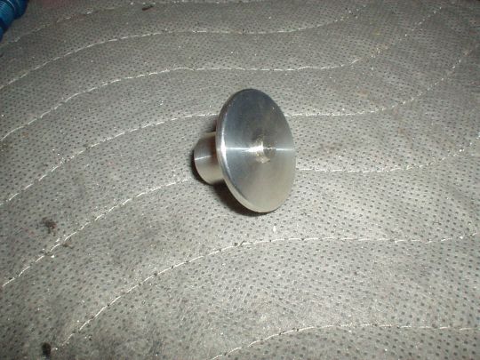
STATIC PORTS
I purchased a pair of machined aluminum static ports from SafeAir1.
These ports have a disk-shaped flange that gets riveted to the inside
of the skin, with only a 1/4" diameter disk protruding through
and approximatly 0.040" outboard of the skin (see below about the
protrusion). The inboard side of the port has an 1/8" NPT
female thread. That seems like a far more robust installation
than Van's pop rivet. I fitted these to the fuselage 1/4"
forward of Van's suggested static port location so there's sufficent
clearance between the static port flange and the bulkhead. Van's
tech support confirmed that the 1/4" deviation should be
negligible.
About the protrusion, there seems to be a lot of conflicting opinions
from a variety of sources, and not much hard data. First of all,
Van's standard pop rivet protrudes outboard of the skin approximately
0.040", and according to Van's "the protruding rivet head
seems to have little to no effect". Several sources that
are more theoretical (including AC 43.13-1B section 12-54) suggest
that the most accurate static port design should be completely flush
with the skin. To the contrary, anecdotal statements from some
RV builders that have actually tried it indicate that a completely
flush static port in an RV actually produces significant static
pressure error (which nobody seems to quantify). Not having
access to sufficient good data to support one or the other, I decided
to keep the 0.040" protrusion on my ports. I'll collect my
own data once I'm flying and make any adjustments if necessary.
Note that everybody who talks about static pressure error seems to
talk in terms of error in indicated airspeed for some reason. Is
it just that everybody is obsessed with speed? To me it seems
that error in indicated altitude would be far more consequential, as
accurate vertical navigation plays an important role in preventing us
from colliding with other flying pieces of aluminum or stationary
pieces of granite. Error in indicated altitude incidentally
should also be easier to measure in isolation. Indicated
altitude is dependent on static pressure only -- it is completely
independent of the pitot ram air pressure and its errors. It can
be measured on the ground or in the air to see if indicated altitude
varies relative to GPS altitude as a function of airspeed and/or power
settings.
PLUMBING MATERIALS
Van's supplies a cornucopia of polypropylene, tygon, and other
unidentified varieties of plastic tubing, and a mix of Nylo-Seal
fittings and some unidentified plastic hose barb fittings.
Yuck. I wanted to find out what is the best choice available,
and use it. A little bit of research online yielded the
following options:
1. Soft aluminum tubing with AN flared fittings
2. All "Nylo-Seal": "Nylo-Seal" nylon tubing with
"Nylo-Seal" nylon compression fittings
3. All "Poly-Flo": "Poly-Flo" polyethylene tubing
with "Poly-Flo" brass compression fittings
4. Mix and match: "Nylo-Seal" nylon tubing with
"Poly-Flo" brass compression fittings
5. Mix and match: "Poly-Flo" polyethylene tubing with
"Nylo-Seal" nylon compression fittings
Note that "Nylo-Seal" and "Poly-Flo" tubing and
fittings are all made by Imperial
Eastman, and are widely available from online retailers, including
Aircraft Spruce. "Nylo-Seal" and "Poly-Flo"
tubing and fittings can be mix-and-matched, with certain restrictions,
according to the manufacturer.
My online search also led me to Brian Gerdes of Gerdes
Aviation Services in Fullerton. Brian specializes in
pitot-static testing, and was described as incredibly knowledgeable by
other RV builders that have received his services. I sent him an
email soliciting his advice, and the following morning he sent me a
detailed reply full of great information and recommendations.
Wow! Here are the key excerpts:
"I always recommend option 5 from your list - Poly Flo hose
with Nylo Seal fittings. The second best for me is all aluminum AN
fittings and hoses.
With option 5 you get: very easy to install, modern look, very leak
proof when done right, and most important to guys who do what I do;
very easy to troubleshoot leaks.
All AN fittings and tubing offers most of these same qualities but is
not as easy to install and not as easy for me to troubleshoot in the
future; compared to option 5.
Option 5 has one basic downfall which is the plastic hoses and
fittings should be replaced at about 15-20 years due to becoming
brittle and shrinkage resulting in leakage. Many Cessnas however have
this same system and are only now just starting to leak 30-35 years
latter. The time varies depending on factors like heat and light
exposure.
The negative side to the metal and AN system is that it's much more
difficult to alter as system changes are needed, more difficult to
troubleshoot, and is very dependent on the installer doing good
quality flares to the tube ends. Also, this system will eventually
have corrosion issues depending on environmental exposure.
Overall, option 5 and AN all aluminum are both good ways to go. My
personal preference is option 5 , but either of these 2 is a good
choice.
If you go with option 5 just be sure to remember that this is a
compression fitting system so you have to remember to use the inserts
in the hose ends( PN# 259-N in the Aircraft Spruce catalog.) or it
will leak. Many people forget these because the catalog does not make
it clear that they are needed.
Also, with either system you want to be sure to use either pipe
sealant with Teflon or Teflon tape on the threads of any pipe thread
fittings going into instruments or encoders. The system will also leak
if you don't do this. I prefer pipe sealant with Teflon. ( available
at Home Depot/ Lowes, etc)
This applies to only pitot/static systems, thread sealant is generally
considered a no/no on vacuum systems due to the possibility of getting
sucked in to the system and lodging in rotor bearings.
Nylo-Seal tubing is very rigid and hard to work with. It is somewhat
like lexan. Trust me, you don't want to plumb your static system with
it."
I'll be going with option 5, as Brian recommended. I will
certainly also go to him when it's time to do my pitot-static
testing. I always value and appreciate people like him who are
not only extremely competent and knowledgeable in their craft, but
also generous in sharing their knowledge with others. |
| 2008.07.30: (0.0)
Van's drawings and text vaguely describe the routing of the static air
line along the longeron from the static ports forward through bulkhead
F-724, then you're on your own. Others have routed their static
lines through the baggage compartment and through the cockpit to the
panel in a variety of ways, under the canopy deck, under the armrest,
under the floors, and various combinations thereof. None are
ideal. Ideally, I would like the line to run as directly as
possible, with no major low spots (potential for water trapping), no
excessive heat, and preferably hidden for aesthetic reasons, but more
so so that it can't get snagged by occupants and/or baggage.
What I settled on was to run the line under the canopy deck, so all of
those requirements are met, at least through the cockpit area.
(In the baggage compartment the line is still not hidden, running
along the longeron per Van's plans.) So this requires 1. a
penetration through the F-705 bulkhead, and 2. some kind of support
for the line under the canopy deck.
The penetration through the F-705 bulkhead will simply be a 1/4"
hole drilled through the bulkhead assembly, including the massive
F-705G support angles. Since this will be going through about a
total 1/4" of material, I think a nicely deburred clean hole with
no grommet should be ok.
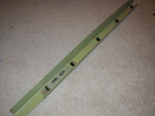
To support the line under the canopy deck, I considered several ideas
including adel clamps, sheet metal "loops" a la Van's DWG 25
"static line attach details", and others. Part of the
problem is making sure that these supports will be accessible and
serviceable when everything's assembled, and also not be in the way
for assembly. I settled on an approach where I made little
support "mini-bulkheads" every 6" or so inside the
canopy deck channel. Each is made of 1/16" x 3/4" x
3/4" aluminum angle, and has a 7/16" hole to accept
an MS35489-6 / AN931-4-7 rubber grommet (or SB437-4 hard plastic snap
bushing).
 |
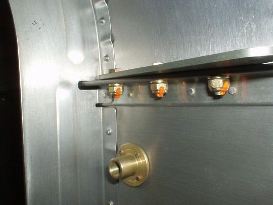
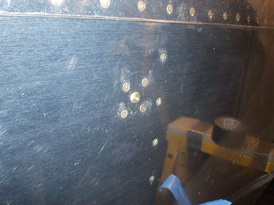
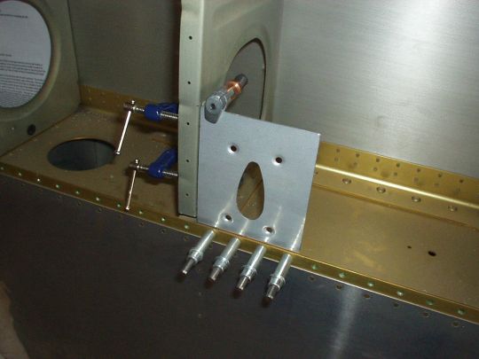
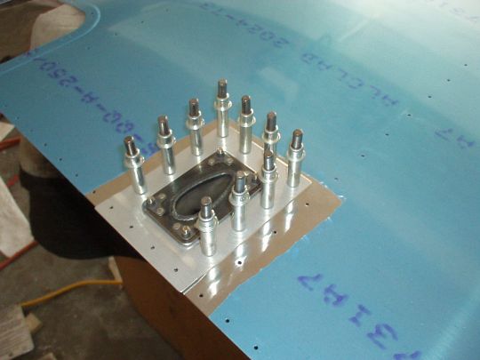
| 2008.08.17: (0.0)
Garnet came over and helped me rivet the static ports to the
fuselage. It's unsupported skin, so it took a little finess with
the gun and bar, but we got it done and the results are nice.
 |
| 2009.05.28: (0.0)
Over to the pitot side.
PITOT TUBE
The standard Van's pitot tube is a piece of 1/4" soft aluminum
tubing bent to an "L" shaped. They also sell a deluxe
version made of stainless steel tubing. This is simple and
inexpensive and an elegant solution for a VFR airplane. But mine being destined for IFR, even though
not for "known ice", I want to have a heated pitot, or at least
the option to upgrade to a heated pitot in the future.
There are a few different standard and non-standard form factors for
pitot tubes, and as best as I could determine the most common one is
AN5812. Pitot tubes in this form factor can be found at
bank-busting prices from certified manufacturers, or a bit cheaper
from the junkyard (i.e from
salvage Cessnas, etc.), or alternatively, more modern non-certified
specimens produced by Angus
Aviation (formerly by Gretz
Aero), by Dynon, and
others. AN5812 pitot tubes do not attach directly to the surface
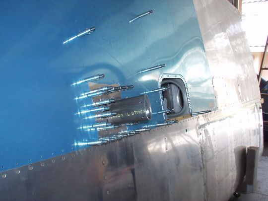
of the wing, but rather to a suitably shaped mount. Gretz
Aero sells such a mount kit that is well suited for the RV.
I purchased one of these kits directly from Gretz and am currently
fitting it to the left wing.
I put some thought into the exact location of the pitot tube.
The standard location of Van's pitot tube is chord-wise just aft of
the main spar, and span-wise in the inboard side of the bay containing
the aileron bellcrank and the outboard-most inspection panel.
This location is probably fine for Van's pitot tube, but is too cramped to
acommodate the larger AN5812 pitot mount. Some folks have
installed their AN5812 pitot mounts in the outboard side of the next
bay inboard, and some folks have installed theirs in the inboard side
of the next bay outboard. Both of these are workable options,
but not ideal. There are a several considerations. 1. For
accurate readings, the pitot tube should be installed in an area where
the airstream is undistrubed, and especially outside the influence of
the prop wash. This dictates that moving the pitot tube outboard
should be ok, but moving it inboard may not be. 2. The pitot
tube should be well clear of the tie-down chains to prevent the
possibility of entanglement and other damage from the chains. The tie-down rings
are located span-wise near the middle of the outboard-most inspection
panel, and due to the RV's short wingspan one would assume that the
tie-down points on the ground will generally be further
outboard. Therefore, the pitot should be located either inboard
of the tie-down rings (as in Van's original design) or sufficiently
far enough outboard of the tie-down rings as to be reasonably assured
that the chains will not come close. 3. For serviceability,
there should be good access to the inside of the wing at the location
of the pitot tube. I chose to install my pitot tube in the
outboard side of the next bay outboard, reasonably meeting all three
criteria.
Note that another option I considered was to install
it in the most outboard bay of the wing, where access would be
provided by removing the wing tip. There, I'd have some worry
that proximity to the wingtip might somehow alter the airflow, but I'm
guessing that it would not that far forward and beneath the
wing. Anyway, maybe I'll try that on my next airplane ;-).
 |
| 2009.05.31: (0.0)
I discovered a minor issue with the Gretz pitot mount. The pitot
tube is meant to attach to the mount using four #6 screws (either
#6-40 or #6-32, depending on the tube manufacturer). The
location of these screws is part of the AN5812 standard, and the holes
are pre-drilled in the Gretz mount to match. The issue I
discovered is that the size of the holes in the mount is too
big. The holes should be approx 0.133" in diameter for a #6
screw to slip through, but the actual holes in the Gretz mount are
approx 0.167", which makes for quite a loose and sloppy
fit. I emailed Warren Gretz about this, and he responded that he
deliberately drills the holes oversized to accomodate variations in
the positions of the holes from one pitot tube manufacturer to
another. I can believe that despite the AN5812 standard there
may be some slight variation out there. However, I would still
have preferred that the mount had been drilled to the correct hole
size, or even undersized. A hole can always be enlarged if
needed, easily. It cannot be made smaller after it has been
drilled too big.
I'll see how the fit looks with the actual pitot tube once I have it,
and go from there. If it's too sloppy and doesn't feel secure,
one option I have is to cut off the end of the mount just above the
holes and drill new ones. Shortening the mount would bring the
tube a bit closer to the wing, which is generally undesireable as it
puts the tube closer to the where the airstream may be affected by the
wing. But a difference that small (approx 1/2") would
likely be insignificant. Anyway, we'll see if that's necessary
or not when I have the tube. |
| 2009.06.07: (0.0)
I selected the Dynon
heated pitot tube, and ordered it from SteinAir.
I had been considering both the Dynon
and the Gretz GA-1000, which
is now manufactured by Angus
Aviation. Both tubes are modern, non-certified, employ
electronics for closed-loop temperature regulation, and are similarly
priced (~$450). I think either would have been a pretty good
choice, but I'll describe some of the key differences between the two
that led me to select the Dynon:
Construction: The Dynon tube is made of machined aluminum, whereas the
Gretz tube is made of molded high-temp plastic. I can't say that
one material is better than the other, just a notable
difference. I suspect that both are well made. The Gretz tube appears to be phsycially smaller, and
therefore may be a bit lighter than the Dynon tube. But I only
have the exact specifications for the Dynon, not the Gretz (see
"Documentation" below) so that's just a guess. And the
Dynon is actually quite light (7 oz. pitot plus 5 oz. controller box),
so any difference in weight between Dynon and Gretz, either way, is
probably fairly insignificant.
Angle of attack port: The Dynon tube, has a second port in addition to
pitot that's used by Dynon's EFIS systems to determine angle of
attack. This particular port arrangement is proprietary to
Dynon, and is different from ports or vains used by other AoA
instruments on the market. Since I'm not planning on a Dynon
EFIS (at least not as my primary, maybe as a backup), this AoA port will remain unused in my airplane. I will
simply plug that tube inside the wing, and otherwise it's a don't
care.
Regulator electronics: Both tubes are supplied with an electronics
module that monitors the tube's embedded temp sensor, controls power
delivery to the heating element, and provides outputs to the cockpit
annunciator(s). And in both cases, this module must be installed
inside the wing in close proximity to the tube. In the Dynon
case however, this module is packaged inside an aluminum enclusure
with mounting flanges, whereas the Gretz is simply an exposed PCB with
mounting holes. I'm actually not too worried about the Gretz
module lacking an enclosure (I'm not sure that Dynon's enclosure
really gives it any significant protection from the elements either),
but looking at how the Gretz PCB is put together gives me pause.
It looks like the board was fabbed using a home etch kit, no
soldermask (potential for corrosion of traces), uses tall unsupported
through-hole components (potential for failure due to vibration), and
uses a relay for power switching (relatively poor-reliability
component). To be fair, I don't know that what's hiding inside
Dynon's enclosure is any better. But Dynon's core business is
its line of EFIS systems, which demonstrates at least that they
possess the know-how to design and manufacture electronics to more
professional standards. So I'm inclined to give Dynon the
benefit of the doubt on this aspect.
Annunciators: Both tubes support annunciators to alert the pilot to
the state of the pitot heat, but they are quite different from each
other in their approaches. The Gretz tube comes with a second
little PCB with three LEDs on it (green, yellow, and red) that
indicate state information regarding temperature and power
delivery. Some of the conditions indicated by individual LEDs
are mutually-exclusive and some are not, some represent fault
conditions and some are normal... My impression is that this
three-LED presentation is both excessive and somewhat confusing,
simply more information than the pilot really needs or wants from the
pitot tube to deal with in flight. Also, this LED board is meant
to be mounted to the instrument panel, but given the physical form
factor of this board, there is no obvious way to do so in a robust or
even minimally elegant manner. Dynon's approach on the other
hand was to support a single annunciator that indicates that the pitot
heat is not operating, either because it is switched off (i.e. no
power being delivered to the regulator module) or because a
malfunction is detected. Dynon's annunciator functionality is
consistent with FAR 23.1326, and while I'm not legally required to
meet this reg, I happen to agree with this being a good idea. This annunciator would be considered a "caution"
condition, and should therefore be annunciated with an amber-colored
light (see FAR 23.1322). Now, unlike Gretz, Dynon does not provide the
actual annunciator light at all, but rather just a current-sink (i.e. "open-drain") output
from the regulator box to drive an annunciator light. That's fine by
me, as I will want to either build my own uniform-looking annunciator
panel anyway, or simply run the annunciator signal into an input on my
EFIS.
Documentation: All of these heated pitot tubes aren't terribly
complicated, but... Angus
has a few general paragraphs on their website (and the same text
is also still posted on the Gretz website, where it originated), whereas Dynon
has a very comprehensive document detailing the specifications,
construction, installation, and operation of their tube.
Warranty and support: Dynon is now a well-established company enjoying
good success with its EFIS line, is located in the United States, and
warrantees their pitot tube for three years after shipment.
Angus Aviation is a newcomer to the scene and still relatively
unknown, presently making/selling only the Gretz pitot tubes and
mounts, is located in Australia, and makes no mention of any warranty
terms on its website (and I didn't ask). Both Dynon and Angus
tubes are also sold through reputable dealers in the U.S. including
SteinAir and Aircraft Spruce, so I suspect that in the short term at
least, good support can be obtained through these dealers. But considering long-term
support from the manufacturer, Dynon seems like the safer bet. |
| 2009.06.27: (0.0)
I received my Dynon heated pitot tube from SteinAir. First
impressions are that it is well designed and well manufactured (a few
surface blemishes, but acceptable). The fit to the Gretz mount
is very good, slipping in easily but snugly, and matching the outer
contour quite nicely (surprisingly a much better fit than the Gretz
pitot tubes to the Gretz mount, from what I've seen).
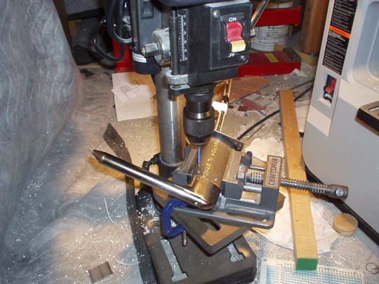
The Dynon pitot tube comes undrilled for the four mounting screws, so
drilling and tapping them was my first task. I slipped it into
the Gretz mount to locate the holes, and I positioned it in a drill
vise with shims to set the drill angle perpendicular to the tangent of
the mount's curved contour. Note that some AN5812 pitot tubes
use #6-40 fine thread screws and others use #6-32 coarse thread
screws. Dynon recommends #6-32, so that's what I used.
 |
| 2009.07.03: (0.0)
Tonight I bench tested my Dynon heated pitot tube for the first time. Here are my observations:
Heat distribution: The tip of the pitot mast became hot within seconds, and then the heat slowly spread aft. So it looks like the heating element is located at the very tip of the mast. I then let it do its thing for about 25 minutes, more than long enough to reach steady state (also evidenced by the fact that the duty cycle had stabilized). At this point, the tip of the mast was very hot to the touch, with temperature decreasing aft toward the base of the mast, which was only warm to the touch. The 3/16" aluminum tubes were not even warm, couldn't have been more than a few degrees above ambient, if that. You wouldn't know by touching them that the pitot heat is even on.
[I don't have real temp measurements. Didn't have a thermocouple on hand. But these qualitative measurements are more than good enough.]
Given these observations, I now have high confidence that plumbing it with plastic tubing will not be an issue temperature-wise.
Power consumption: The current draw measured about 7.8A when the heating element is on, and about 60mA when the heating element is off.
Once steady state temp was reached, the duty cycle was surprisingly low. The heating element turned on about once a minute for only two or three seconds. Now granted, this is on the bench, with ambient air at room temperature, and no airflow. Under flight conditions the duty cycle should be somewhat higher due to greater rate of heat loss to the airstream. But still I'm surprised at how low it is, at least on the bench.
To my suprise, the control box apparently uses a relay for the status
output, or possibly for powering internal circuitry. I can hear
it click shortly after applying power to the control box, and again
shortly after removing power from the control box. No click is
heard as the control box cycles power on and off to the pitot mast, so
that apparently is done with solid state devices. So Dynon has
the know-how for switching a high-current load with a solid state
device... I wonder why they opted for a relay in the other case.
Curious.
Overall, my impression of this tube so far is very positive. Well designed, well made, and works well to the extent that I've been able to test it so far. Good job, Dynon!
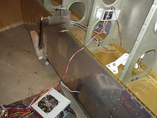
Control box mounting: I decided to install the control box in the same
bay as the aileron bellcrank to provide good access to it through the
access hatch. I selected the outboard rib, between the first and
second lightening holes. I installed #6 nut plates at this
location, matching the control box's mounting holes. Note that
mounting box sits right over the convex side of a stiffener bead in
the rib, so spacers have to be used between the control box and the
rib so that the box clears the bead. About 0.090" spacer
thickness (three standard washers) is more than adequate. Note
also that I haven't determined yet which way the box will be
oriented. It has the pitot wires coming out on one side, and the
airframe wires coming out on the other side, so wire routing will be
the determining factor.
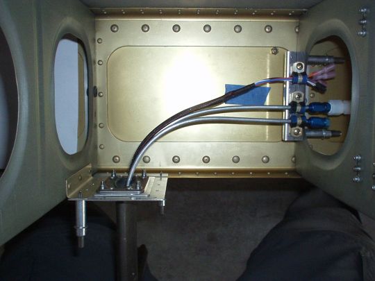
Plumbing: Since the Al tubes don't seem to heat up significantly, I
decided to plumb the pitot line with flexible plastic tubing (poly-flo
tubing and nylo-seal fittings). Firstly though, the Al tubes
coming out of the pitot. I decided to keep their full length and
just bend them very gradually about 90° inboard toward the lightening
hole in the rib. I didn't use a tubing bender, but rather just
bent them gently over my knee. By keeping a very wide bend
radius, I ensured that it is still possible to insert and remove the
pitot tube, plumbing and all, through the Gretz mount which is mounted
in the wing.
The transition from the 3/16" Al tube of the pitot to the wing
plumbing is as follows:
- AN818-3D nut, 3/16" flared tube
- AN819-3D sleeve, 3/16" flared tube
- AS4824A03 conical seal, 3/16" flared tube
- AN816-3D nipple, 3/16" flared tube to 1/8" male NPT
- teflon thread sealant on NPT threads
- 266N-04X02 nylon connector, 1/8" female NPT to 1/4"
plastic tube (compression fitting)
Similarly, I capped off the unused AoA line on the Dynon pitot tube as
follows:
- AN818-3D nut, 3/16" flared tube
- AN819-3D sleeve, 3/16" flared tube
- AS4824A03 conical seal, 3/16" flared tube
- AN806-3D plug, 3/16" flared tube
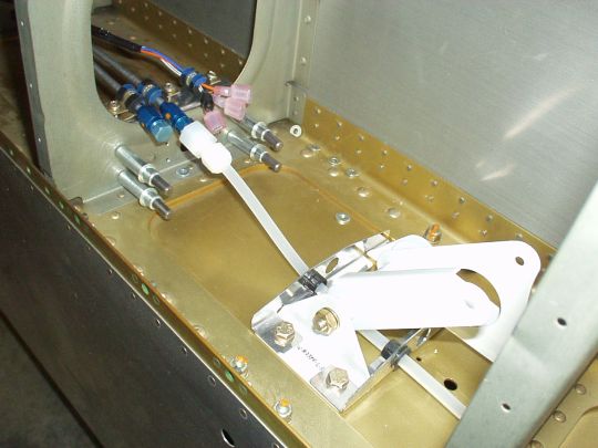
Now I need to fabricate a couple of brackets to support the tubing and
guide it safely through the rib lightnening hole and around the
aileron bellcrank.
|
|
|